


| Quantity: | |
|---|---|


Product Introduction
Measuring diameter | (DN10-DN2000) other specifications can be customized |
Accuracy level | ±0.2~0.5 |
Conductivity | ≥50us/cm |
Protection level | IP65, IP68 |
Power supply | AC220V/DC24V (standard); battery power supply can be customized |
Communication mode | RS485, Modbus, GPRS, Profibus-dp, Hart, Wifi, etc. |
Installation method | default flange connection (flange connection, thread, clamp can be customized) |
Structure Chart
 |  |  |
Structure Chart
 |  |  |  |
| 1.Craftsmanship The product body is smooth and has exquisite processing technology. The product paint surface is moisture-proof and rust-proof |  |
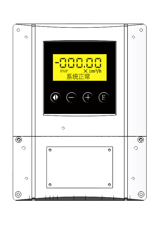 | 2.Smart meter Clear real-time flow display, cumulative flow display, support Modbus, Profibus-dp, GPRS, Wifi, Hart and other communication protocols, support remote APP function |
3.Non-magnetic stainless steel body Using high-quality non-magnetic conduit Effectively reduce on-site measurement interference |  |
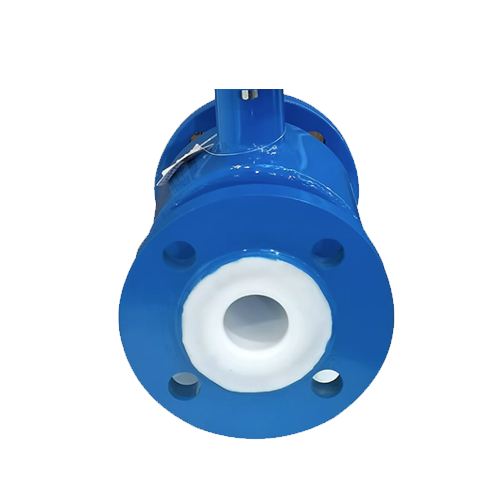 | 4.Triple-proof lining Adopts anti-shedding, anti-flapping and anti-leakage materials, improves the reliability of instrument use |
The shell is tough and wear-resistant. The shell made of professional customized steel and advanced laser welding technology are adopted. | Upgrade converter Upgrade converter, with more stable performance, zero drift, lower repeatability and more accurate measurement. | Pure copper coil Adopting national standard pure copper coil, professional customization, double-layer insulation and isolation, more reliable performance and longer service life. |
 |  |  |
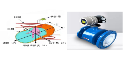
According to Faraday's electromagnetic induction principle, detection electrodes are installed on the wall of the measuring tube where the axis of the measuring tube is perpendicular to the magnetic field lines. When the conductive liquid moves along the axis of the measuring tube, the conductive liquid cuts the magnetic field lines to generate an induced potential. This induced potential is detected by the detection electrode, and the value is proportional to the flow rate. Its value is: E=KBVD In the test:
E-induced potential
K-coefficient related to magnetic field distribution and axial length
B-magnetic induction intensity
V-average flow rate of conductive liquid
D-electrode spacing (diameter inside the measuring tube)![]()
Range selection table
| Velocity-flow comparison table | |||||||
| Velocity | 0.01 (Min) | 1 | 2 | 3 | 4 | 5 | 15 (Max) |
| Latus Rectum | |||||||
| 15 | 0.0113 | 0.6362 | 1.2723 | 1.9085 | 2.5447 | 3.1809 | 9.5426 |
| 20 | 0.0177 | 1.1310 | 2.2619 | 3.3929 | 4.5239 | 5.6549 | 16.9646 |
| 25 | 0.0452 | 1.7671 | 3.5343 | 5.3014 | 7.0686 | 8.8357 | 26.5072 |
| 40 | 0.0707 | 4.5239 | 9.0478 | 13.5717 | 18.0956 | 22.6195 | 67.8584 |
| 50 | 0.1195 | 7.0686 | 14.1372 | 21.2058 | 28.2743 | 35.3429 | 106.0288 |
| 65 | 0.1810 | 11.9459 | 23.8918 | 35.8377 | 47.7836 | 59.7295 | 179.1886 |
| 80 | 0.2827 | 18.0956 | 36.1911 | 54.2867 | 72.3823 | 90.4779 | 271.4336 |
| 100 | 0.6362 | 28.2743 | 56.5487 | 84.8230 | 113.0973 | 141.3717 | 424.1150 |
| 150 | 1.1310 | 63.6173 | 127.2345 | 190.8518 | 254.4690 | 318.0863 | 954.2588 |
| 200 | 0.2827 | 113.0973 | 226.1947 | 339.2920 | 452.3893 | 883.5729 | 1696.4600 |
| 250 | 1.7671 | 176.7146 | 353.4292 | 530.1438 | 706.8583 | 1272.3450 | 2650.7188 |
| 300 | 2.5447 | 254.4690 | 508.9380 | 763.4070 | 1017.8760 | 1731.8030 | 3817.0351 |
| 350 | 3.4636 | 346.3606 | 692.7212 | 1039.0818 | 1385.4424 | 2261.9467 | 5195.4089 |
| 400 | 4.5239 | 452.3893 | 904.7787 | 1357.1680 | 1809.5574 | 2862.7763 | 6785.8401 |
| 450 | 5.7256 | 572.5553 | 1145.1105 | 1717.6658 | 2290.2210 | 3534.2917 | 8588.3289 |
| 500 | 7.0686 | 706.8583 | 1413.7167 | 2120.5750 | 2827.4334 | 5089.3801 | 10602.8752 |
| 600 | 10.1788 | 1017.876 | 2035.7520 | 3053.6281 | 4071.5041 | 6927.2118 | 15268.1403 |
| 700 | 13.8544 | 1385.4424 | 2770.8847 | 4156.3271 | 5541.7694 | 9047.7868 | 20781.6354 |
| 800 | 18.0956 | 1809.5574 | 3619.1147 | 5428.6721 | 7238.2295 | 11451.1052 | 271,433,605 |
| 22.9022 | 2290.2210 | 4580.4421 | 6870.6631 | 9160.8842 | 14137.1669 | 34353.3157 | |
| 1000 | 28.27437 | 2827.4334 | 5654.8668 | 8482.3002 | 11309.7336 | 20357.5204 | 42411.5008 |
| 40.7150 | 4071.5041 | 8143.0082 | 12214.5122 | 16286.0163 | 27708.8472 | 61027.5612 | |
| 1400 | 55.4177 | 5541.7694 | 11083.5389 | 16625.3083 | 22167.0778 | 36191.1474 | 83126.5416 |
| 72.3823 | 7238.2295 | 14476.4589 | 21714.6884 | 28952.9179 | 28952.9179 | 108573.442 | |
| 1800 | 91.6088 | 9160.8842 | 18321.7684 | 27482.6525 | 36643.5367 | 45804.4209 | 137413.2627 |
| 113.0973 | 11309.7336 | 22619.4671 | 33929.2007 | 45238.9342 | 56548.6678 | 169646.0033 | |
| 2200 | 136.8478 | 13684.7776 | 27369.5552 | 41054.3328 | 54739.1104 | 68423.8880 | 205217.6640 |
| 162.8602 | 16286.0163 | 32572.0326 | 48858.0490 | 65114.0653 | 81430.0816 | 244290.2448 | |
| 2600 | 191.1343 | 19113.4268 | 38226.8536 | 57340.2804 | 76453.707 | 295567.134 | 286701.402 |
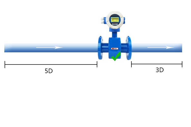
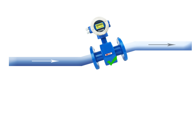
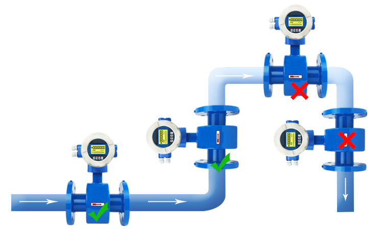
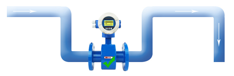
| 1.There needs to be at least a 5*D (D is the inner diameter of the flow meter) straight pipe section in front of the flow meter and a 3*D straight pipe section behind it. | 2.Should be installed at the rising part of the pipeline | 3.Install it at the lower part of the horizontal pipe and vertically upward, avoid installing it at the highest point of the pipe and vertically downward. | 4.When installing in an open discharge pipe, it should be installed at the lower part of the pipe. |
 |  |  |  |


